MEV Exocet UK Build Guide
Build Guide
MEV EXOCET UK BUILD GUIDE
Dismantling the Miata Donor
Warnings:
Please be careful when removing the tops from the shock absorbers on the MX5. They are under tension and ready to fly once you have removed the weight of the body shell.
The fuel tank should be emptied before you remove the body shell to help balance.
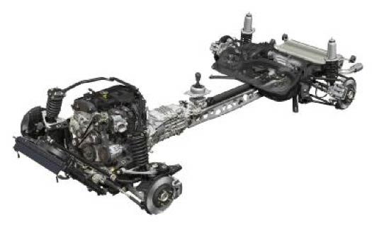
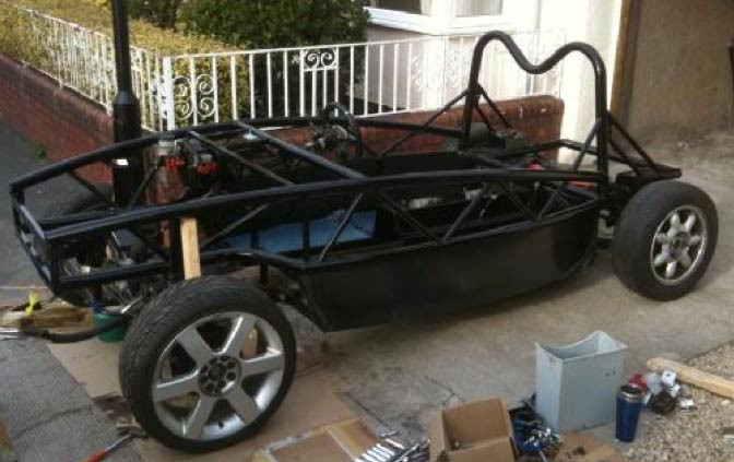
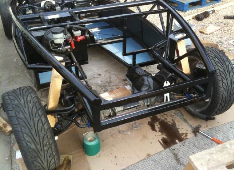
The aim is to remove the body shell and leave the front sub-frame with the engine, and the rear sub- frame with the differential, connected together via the alloy back bone, as seen in the picture below.
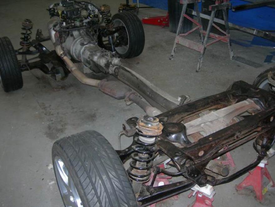
The picture below shows a 200mm long piece of tube that is inserted in to each corner of the suspension so that the rolling chassis may indeed roll without the engine and diff sinking.
The rolling backbone that you will have left can be stripped to replace bushes if required, and to properly detail, clean and paint all the suspension parts, brakes and sub-frames.
First remove battery from the boot then push the cables down through the floor.
The engine bay fuse box can be left attached to the starter/alternator, the cables going through the bulkhead can be unplugged at the fuse box, the cables going to the battery can be left attached to the power plant frame. The PPF is the alloy beam that joins the gearbox to the diff housing.
Now jack up the car and place on good solid axle stands for access to the underside.
Next, remove the seats, seat belts, and carpets.
Then remove the 2 plastic caps from each side of the dash board and remove the 4 bolts.
Remove the plastic cap from the top centre of the dash and remove the bolt below it.
Remove the 2 air vents above the radio and remove the screws. Pull off radio panel.
Remove the 2 bolts either side of the radio then remove the instrument surround.
Remove the speedometer plugs and cable and then remove the instrument unit.
Next, remove the steering column and shaft that connects it to the rack.
Now lift out the whole dash unit to gain access to the wiring harness/loom.
Unplug all the cables going to the fuse box to allow them through the bulkhead.
All cables can now be pulled back from the engine bay and battery into the cockpit.
It looks complicated but all you need to do is plug it all back where it was.
MAKE SURE YOU LABEL EVERYTHING.
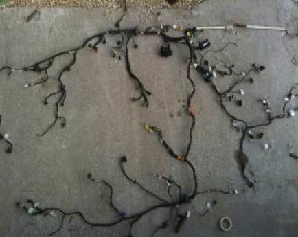
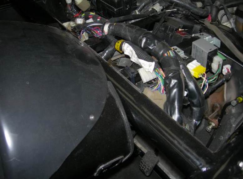
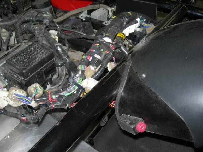
Many of the plugs you see in the loom pictured below will not be re-connected. No heater, wipers, interior light, cig socket, radio, electric mirrors, speakers, window motors, headlight lift motors, glove box light, etc. It is possible to strip the loom back to remove all these plugs but I just left the fuses out of the items not required. Quite a lot of cable to bunch up under the bonnet though but I suggest you run the Exocet to make sure you have everything correct before you start modifying the loom.
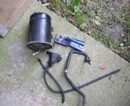
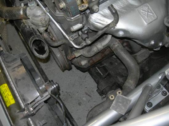
The picture above on the right shows the engine bay charcoal canister which can be left off.
There is a pipe that feeds from it back to the tank. This can be blanked off. The pipe from the cam shaft cover to the canister will also need blocking off.
The MX5 has a large steel bodied fuel filter which is mounted near the tank. This can be replaced with an in line filter that is suitable for fuel injected cars (not plastic bodied).
You will probably also replace the 2 fuel pipes (feed and return) with rubber. Please ensure that the pipe you use is suitable for fuel. It is usually marked. The IVA inspector may ask for proof of this.
Check to see if your donor has a back light dim facility for the dash. If it has you will need to retain the dimmer unit from the dash, as back lights are required for IVA.
If the donor is an import, check that the fog light only comes on when you have the headlights on. Again this is an IVA requirement.
Remove the throttle cable and clutch master cylinder leaving it attached to the gearbox.
Remove the brake pedal and servo, and clutch the pedal.
Remove all electrical connections and plugs from the engine. Label them as you go.
Disconnect the 2 fuel pipes from the fuel rail on the left of the engine. They may be under pressure. Remove the air box and un-plug the air flow meter that is attached to it.
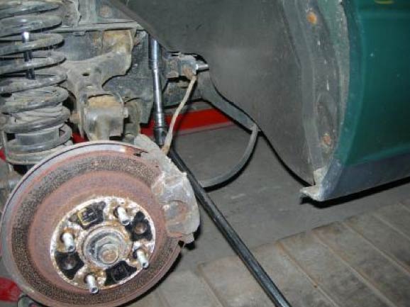
Remove the radiator, and air con if fitted. Careful as this may be pressurised. Unscrew the 2 front brake pipes noting where they are connected from.
Cut or unscrew the rear brake pipe at the junction on the rear axle. Disconnect the handbrake cables from the rear callipers.
Support the underside of the front and rear sub-frames with substantial props or use short tubes to support the suspension as shown in the previous picture.
Remove the speedometer cable from the gearbox.
Remove the centre nut on the top of each shock absorber. If you remove the 2x8mm bolts on the top instead then the springs will be compressed and dangerous to remove later for cleaning or painting. Remove the six bolts holding the rear sub-frame to the body shell. Clean and oil the threads first.
Remove the eight bolts holding the front sub-frame to the body shell. A 1m long bar may be needed.
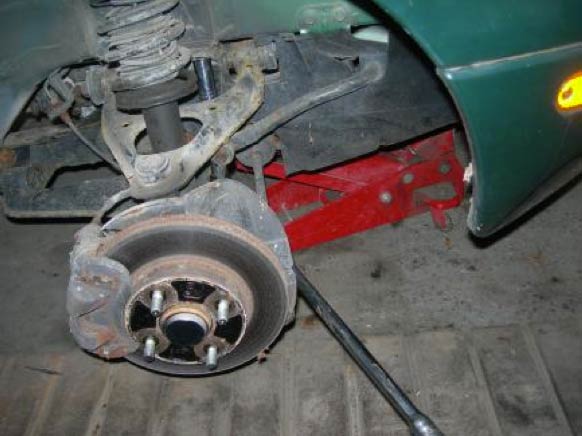
If you intend to remove the hubs for cleaning/painting then do so before you disconnect the brakes so you can lock them on and undo the nuts.
Lift off body with an engine hoist leaving the 2 sub-frames connected by the alloy back bone.
This is best achieved by attaching a lifting chain to the front left and rear right seat bolt holes as the balance is about right.
You can now remove the tank, filter, handbrake and cables.
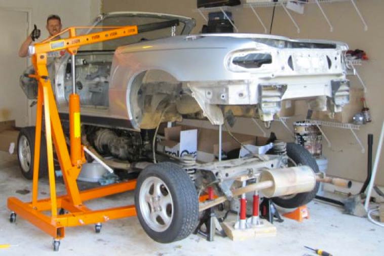
The stripped out body shell weighs around 250 kgs. It is suggested that the doors are removed and all of the interior is removed before lifting the body off to reduce the weight.
Don’t forget that once the load is taken from the top of the shock absorbers then the sub frames will sink to the ground unless propped up or tubes are inserted as per the picture shown previously. Ideally you should have a trailer ready so the shell can be loaded and taken to a scrap metal merchant who will pay around £60 for the scrap. Don’t forget any odd bolts or screws or rubber capping may well come in handy later.
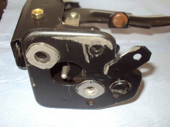
It is recommended that pictures are taken of the donor and that the VIN number on the front bulkhead is cut out before it is scrapped. Below is what Mazda call the power plant frame.
Preparing the Exocet Chassis
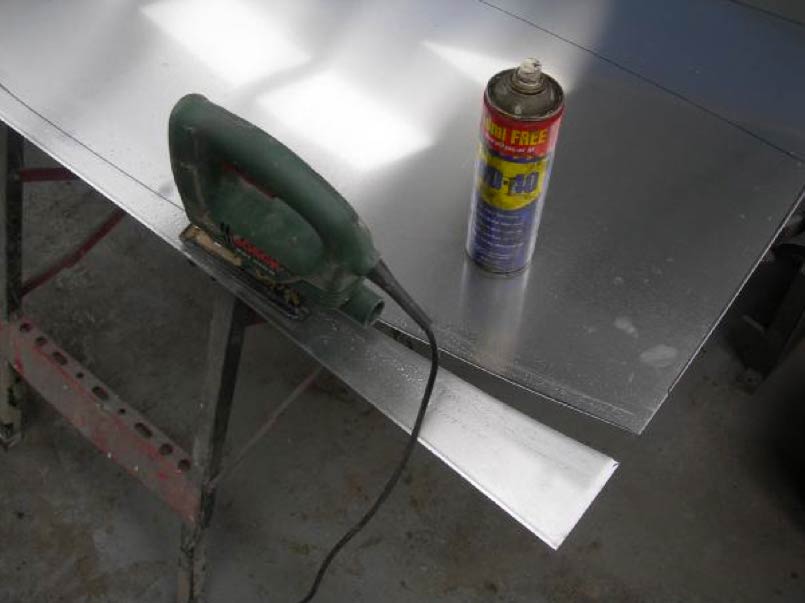
Now we can cut the alloy floors as shown in this picture, you lay the chassis on the alloy, mark around it with a felt pen and then cut with a jigsaw with a fine blade.
You will need a lubricant to stop the alloy from clogging the teeth of the blade. WD40 works fine. Just spray it along your line before you commence cutting.
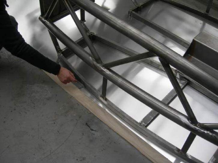
Next job is to rivet the floor to the chassis. You will need to mark the holes at 100mm centres. You may also use a sealer such as PU or silicone to make the floor and sides water tight.
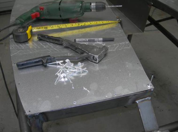
The one in the picture above is not painted of course but all the holes can be drilled before painting. They will need clearing out after though. It is quicker to drill after it is painted. You just need carpet under the chassis so you can turn it upside down without damaging the paint or powder coating.
The plastic sides are easy to trim to shape and fit using self tapping screws at 150mm centres.
It is easy to P clip the rear brake pipe at this time. You can also fix the feed and return pipes for the fuel. You can use 8mm copper for this provided you flare the ends so the pipe does not blow off.
Now you can lower the chassis on to the rolling PPF (power plant frame) and bolt it up.
The one above shows wooden blocks for support and the engine removed.
Below you can see the four (90mm) bolts used to hold the rear sub-frame to the chassis. On 1.8 cars you may find brackets on the lower part of the sub-frame that will line up with the two brackets on the lower edge of the Exocet chassis at the back edge of the floor. Use the supplied 2x 30mm bolts.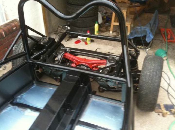
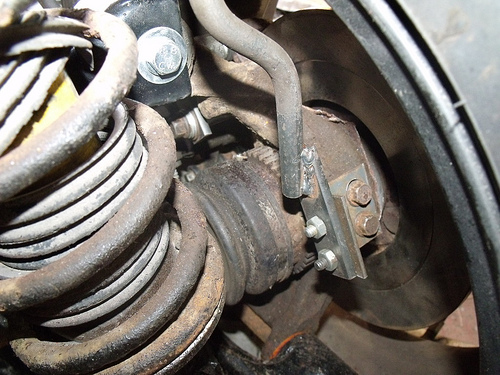
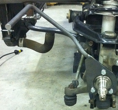
The wing stays come in a set of 8. That’s 2 for each corner. They do differ. You will see from the picture below that the rear pair are attached by drilling 2 holes in the rear upright for one half and the other is simply attached using the top caliper bolt. Use thread lock on the bolts and PU adhesive.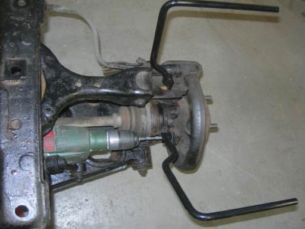
The front pair as shown below are attached to the top ball joint and the top calliper bolt. You may need to grind a small section of the Mazda upright away so that the angle piece of the wing stay sits flat and cannot twist around the top ball joint nut. It should fit tight in the upper corner of the upright.
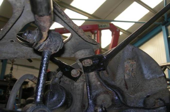
Please see the IVA manual to determine the required positions of the wings. You will need a spirit level to ensure that the wheel rim does not protrude a vertical line from the edge of the wing.
We drill 2 holes for the wings stays to go into and then bond them to the underside with PU adhesive. It is important that thread lock fluid is used on the calliper bolts or/and you should use a longer bolt with a locking washer. The nut from the ball joint will need a split pin in it or a nylock nut.
The wing stays are designed to use 195/45-16 wheels/tyres either with a 32mm spacer for 45 ET wheels or no spacer if you buy 15ET wheels. These can be the cheaper universal type with stud extensions or the better solid indexing ones with replacement studs or separate studs.
These are available from www.rallydesign.co.uk
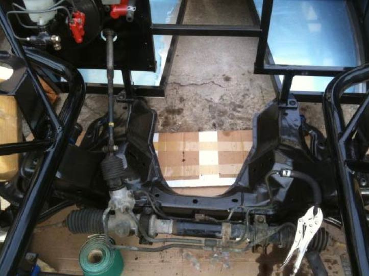
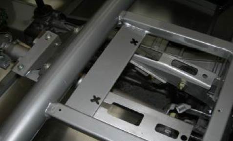
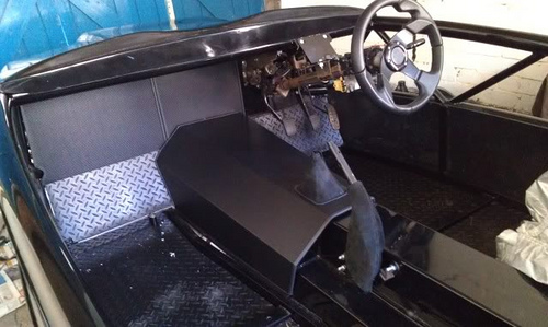
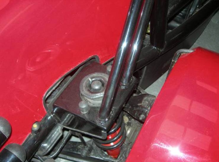
The steering column is shown below together with the pedal assembly and servo installed.
This also shows that in this case the engine has been removed to allow painting of the sub frame.
Above you can see that it is very easy to modify your steering column height to suit
The column alteration only requires two extra holes and the top of the plate cutting off though. Moving the pedal assembly requires a little more work though but do not rule out the option of dropping them by drilling and filing the holes out to suit your feet!
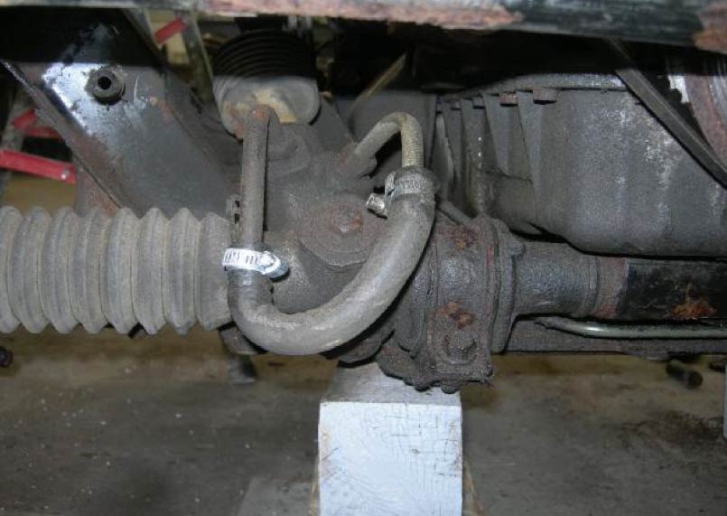
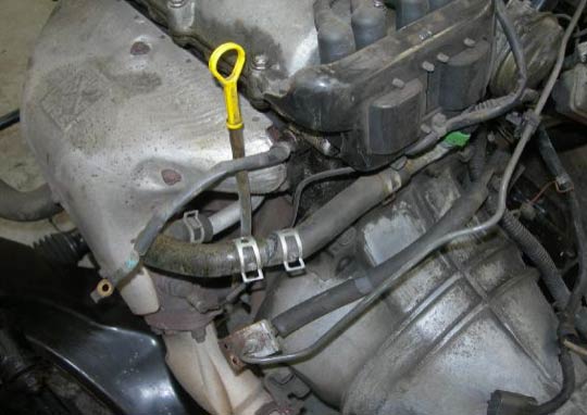
It is possible to cut the feed and return pipes on the power steering rack and join them with a rubber hose. This will save weight and reduce engine load. Exocet is light and does not need power steering.
You may have to cut the spacer tubes off the back of the pedal assembly for the column shaft to reach. Re-use them on the engine bay side of the bulkhead when bolting the servo unit in to place.
Below you can see the use of a stack of washers instead of using the spacer tubes that were cut off. These are on the engine side of the bulkhead and maintain pedal position in relation to the servo.
Here you can see marks for two holes for bolts and spacers to support the brake and clutch pedals via the 6mm thick chassis plate. 2x 8mm bolts will be required.
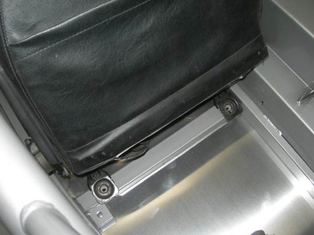
Seat belts are taken from the MX5 and used in the same manner by attaching as shown below.
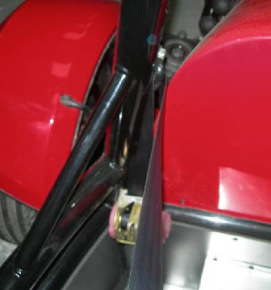
The handbrake needs careful positioning to ensure cable tension before drill to mount it. You may need to drill the rear corner of the tunnel or your nearside cable maybe too short.
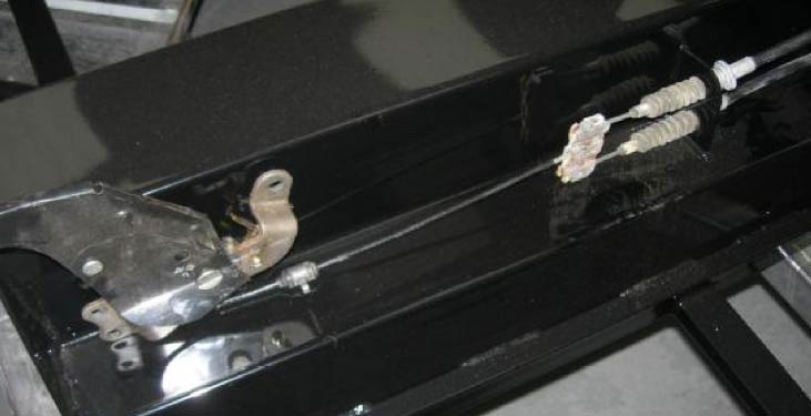
Ensure you connect the handbrake warning switch wire as this is used to test the fluid level indicator light on the dash via the brake reservoir float switch in the clear brake fluid bottle.
Fuel Tank
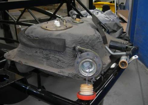
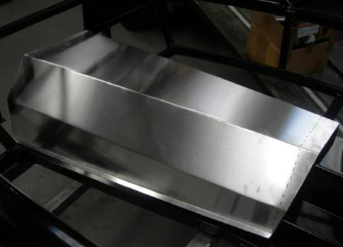
The standard fuel tank can be used and mounted on spacers as shown.
You will also see in this picture that we have used the standard filler neck and cap. The steel part is cut down by 250mm and the large rubber pipe is reduced by 100mm. The pieces that were cut off can be seen on the right of the tank.
For IVA purposes the fuel cap needs to be tethered. It can be done with a bath plug chain as shown.
All you need to do then is cut a hole in the side of the top rear corner of the grp cover for the cap to protrude.
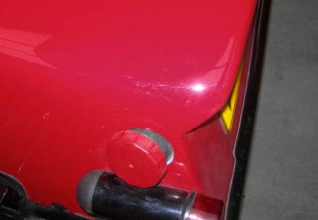
*This does restrict the tank contents to around two thirds though. If you buy a flush fit alloy cap and flexible pipe from CBS then you can mount it in the top nearside rear corner instead. This will allow you to fill the tank completely.
Brakes
If you use the standard MX5 flexible brake pipes you will need to make a bracket to mount them. Ensure that when the steering is on full lock that the pipe is not being pulled tight, you must also allow for suspension travel. You can bolt a piece of 3mm alloy about 100mm long to the sub-frame.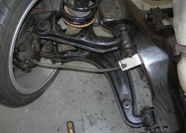
The rear brake pipe junction will need rotating so that it clears the rear bulkhead. In this case we have not replaced the pipe running from left to right across the subframe as it is in good condition.
Note on brake servo pipe:
Important to note that the vacuum pipe going to the brake servo from the inlet plenum has a one way valve in it. Not easy to spot but easy to put it on the wrong way around. We passed an IVA last week with the pipe the wrong way around proving the brakes are good enough without a servo as the car is so much lighter than the car the brakes were designed for. I must say though I much prefer the brakes with servo. The pipe maybe marked with a direction arrow which would mean air flowing towards the plenum for vacuum. To test;
Put your foot on the brake.
Start the engine.
Pedal will be sucked down slightly if servo works.
Wiring
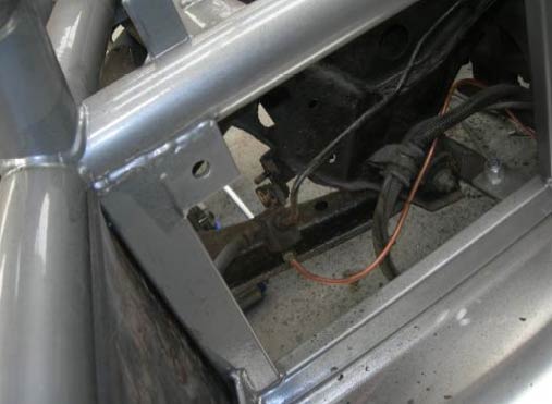
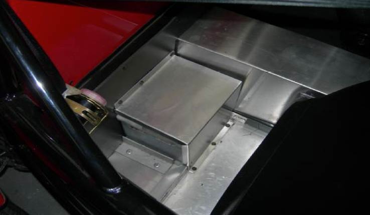
The battery can be mounted behind the seats and a box made to protect it.
EARTH POINTS. Very important. One at battery to chassis, one to alloy beam near diff, one strap from engine to chassis above exhaust manifold. One multiple earth at pedals, and one above the exhaust on front bulkhead (near engine earth strap) and one at the petrol tank for rear lights/pump.
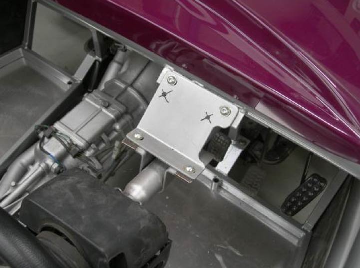
The wiring harness from the MX5 and its fuse block etc can be mounted as shown.
You can also see that the fog and hazard switches can be used by mounting them in a piece if alloy that is made from the floor off cuts. This also closes the gaps around the MX5 instrument surround.
Interior
The alloy for the tunnel and bulkheads will need trimming with a pair of tin snips. You will also need to carefully mark and cut out a hole for the gear lever. Start small increasing when you have tried it.
A hole will need cutting out for the gear lever, it is easier to mark out with the lever removed.
Tips for trimming and installing the aluminum transmission cover:
-Make a template for the front from cardboard going aft about a foot
-Use a hot glue gun to secure some light string front to rear from firewall to rear tunnel to get distant front to rear and how high and were to bend at
-Make two sides and top templates separately then tape together for a trial fit
-When it comes time to cut, take off a small amount at a time and test fit after each cut to ensure you do not remove too much material.
The standard Mx5 seat runners can be bolted on the two chassis rails as shown by drilling 4 8mm holes per seat. Remember to remove the plastic cover from the recline lever to allow more room. The MX5 seats will require the plastic cover for the recline lever removing as they are a tight fit against the center tunnel.
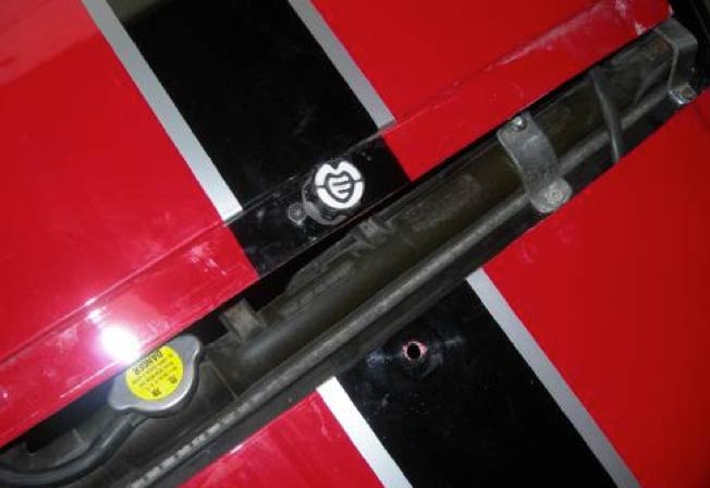
Radiator
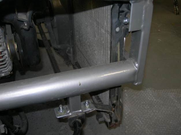
Above you can see an alloy bracket that we made to secure the bottom of the radiator. We then drilled through the chassis and used two 8mm bolts to mount the top through the bushes on the radiator.
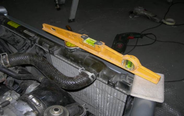
The radiator must not be mounted any higher than shown, the pad above is approx 10mm thick.
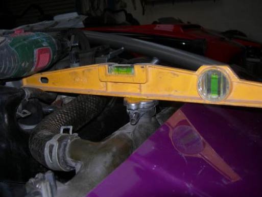
The heater pipes are shown below. These have been joined together with a sleeve as there is no heater to connect them to. I did get a leak on one though so maybe it is best to use jubilee type clips.
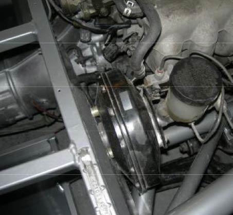
Above you can see we have removed the air con compressor and the power steering pump.
A small alloy bracket can be used to secure the radiator pipe if you are using the Mazda ones.
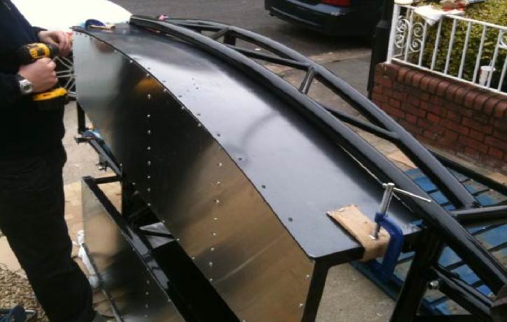
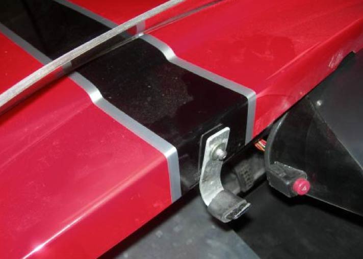
Mounting the GRP Body Panels
The grp can be mounted in several different ways. The simplest is shown below. We mounted a nut on the back of the grp nose and used a knob from an old circular saw.
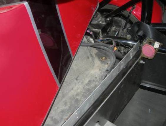
The rear of the bonnet has a curved piece of 3mm thick alloy that fits behind the dash and hooks under the main chassis tube.
Below you can see we used a piece of alloy angle to mount the petrol tank cover.
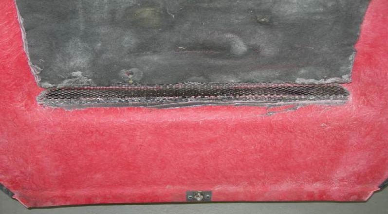
The alloy grille mesh can be trimmed easily with tin snips. It can then be shaped by hand to ensure a good fit to the rear of the hole and bonded in place using PU adhesive. You will notice we also used a matt bonded underside of the bonnet from a scrap car to protect the GRP from heat of the engine.
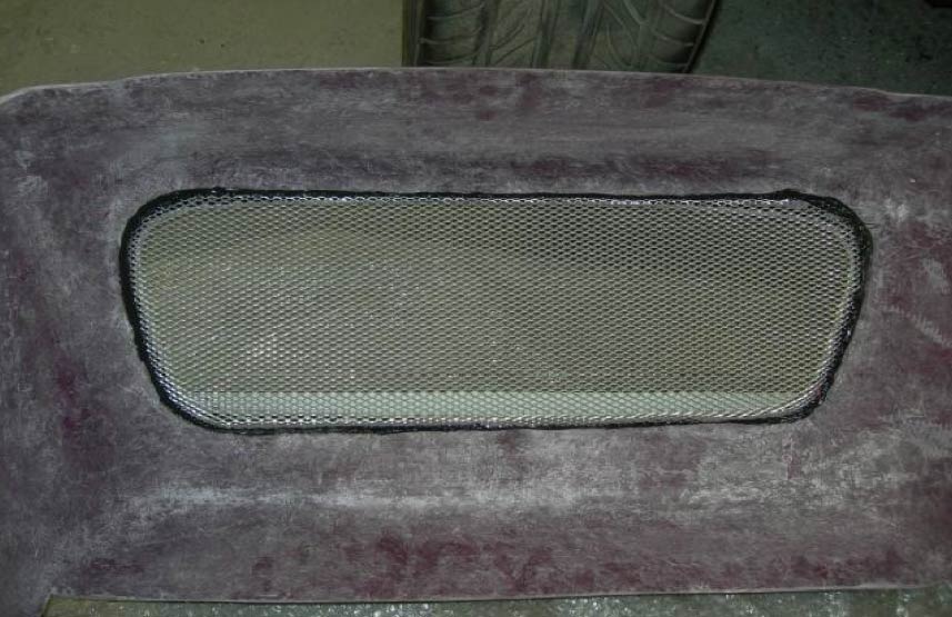
Shown below is the radiator grille that has been bonded in on the inside of the nose cone.
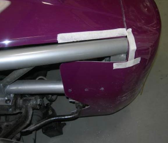
The front grp section can be tilted slightly down on the nose if preferred, just trim the grp on the masking tape line as shown. The bonnet also needs a trim for a flush fit, then add edge trim.
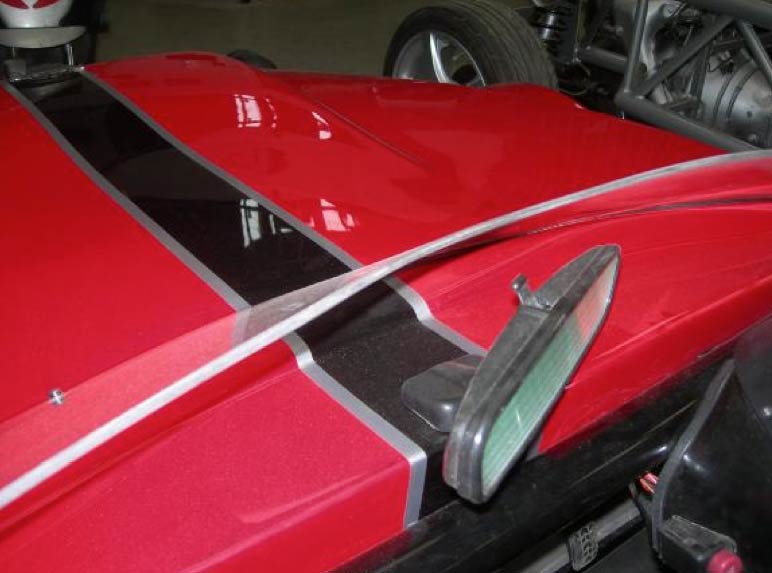
Below you can see a fly screen which is cut from Perspex, if this is fitted prior to IVA then you may need to prove it is shatter proof and not too high so as to be considered a windscreen, leave off!
UK Lighting Positions & IVA Compliance
Lighting positions are very important. If you go to www.mevltd.co.uk and click MEV LTD then click DOWNLOADS and then IVA manual you will see the relevant pages.
Whilst you are in that pdf please pay attention to the requirements for contactable surfaces. In a nut shell if the inspector can contact anything with a 100mmm ball it will need to have a radius of at least 2.5mm. Most of these edges can be capped with knock on edge trim.
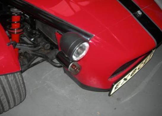
The light emitting surface of the headlights has to be a minimum of 500mm from the ground. All lights except fog and reverse need to be within 400mm off the edge of the wings.
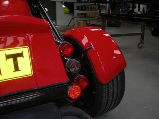
Rear lights need to be a minimum of 350mm from the ground.
Fog light needs to be on the off side and a minimum of 250mm from the ground.
Reflectors need to be upright and again a maximum of 400mm from the outside edge of the vehicle.
Indicators need to be seen from 45 degrees from the opposite side to which they are fixed, they also need to be positioned so that the light emitted is a minimum of 350mm from the ground.
Side repeaters need to be seen at 5 degrees from the side of the car from 3 metres behind.
The tubes can be mounted using self tapping screws from the rear through the GRP.
The fog light must be a minimum of 100mm from the stop/tail lamp. A number plate light is required which comes on with the tail lights. There are various aftermarket options available as the standard MX5 license plate lights are quite large.
MX5 REAR LIGHT WIRE COLOURS; Red/black line=side. Green/white line=right ind. Green/black line=left ind. Green=stop. Red/green line=reverse. Black multi wire block down to chassis near tank.
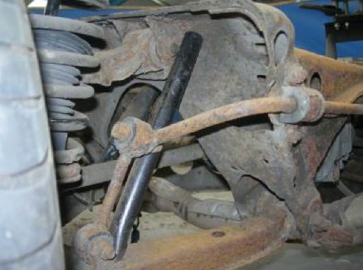
Here you will see edge capping on the wishbones and electrical cable sleeves on the track rod ends.
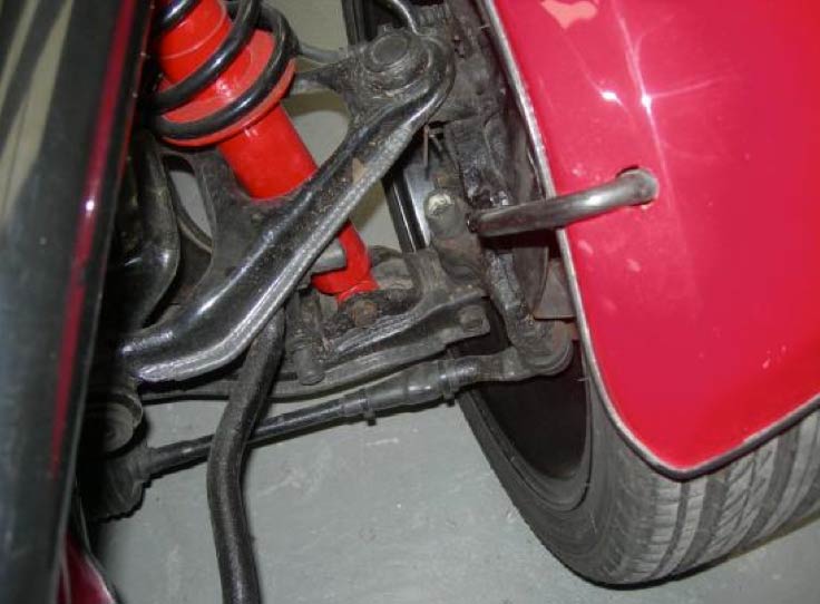
Note the capping below on edges with a radius that is less than 2.5mm. You will need to be very careful that all contactable edges that can be touched with a 100mm ball are capped or protected in order to comply with the IVA test. Also nut caps are shown, again for IVA purposes.
It is a good idea to stick caps and trim on with PU adhesive so they do not come off easily.
Installing Fender Mounts
Overview
The Exocet kit includes eight fender mounts. Two fender mounts are used in each corner. Once installed, the fiberglass fenders can be mounted by drilling appropriate holes and using polyurethane adhesive to bond them to the fender mounts.
The frontmost fender mount is the one with three bolt holes that replaces the stock brake dust shield. The fender mounts that go on the back of the front corner and the front of the back corner are the same size/design and will bolt to the top caliper bolt. The rearmost fender mount is the one with the slightly longer mounting tab, meat to bolt to the nub on the non-ABS rear upright.
Note 1: Depending on the castings of the Mazda uprights and where you drill your hole in the fender mounting tab, you may need to take an angle grinder and remove a little material from the mounting tab on the fender mount for proper/secure fit.
Note 2: The fender mounts are made out of 1/2″ steel bar and are designed to have enough give to be bent a few degrees as needed for final fitting of the fenders. Once bolted down, you can bend them with your hands with a sizable amount of force.
Note 3: You may want to use a little thread locker on bolts, especially the top caliper bolts.
Note 4: In rare cases, some Miata donors may not have a nub on the rear upright and will require a steel angle bracket to be attached to the upright.
Front corner, front mount
Remove dust shield and replace with bolt on mount. Locking washers are recommended.
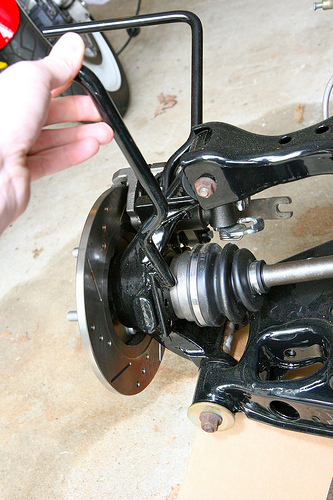
Front corner, rear mount
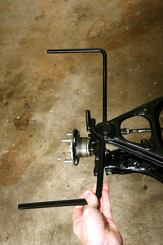
Note the angle and where it fits to be bolted via top caliper bolt.
(Note – the forward mount in this photo is the old style replaced by the new model that bolts to the stock brake dust shield location)
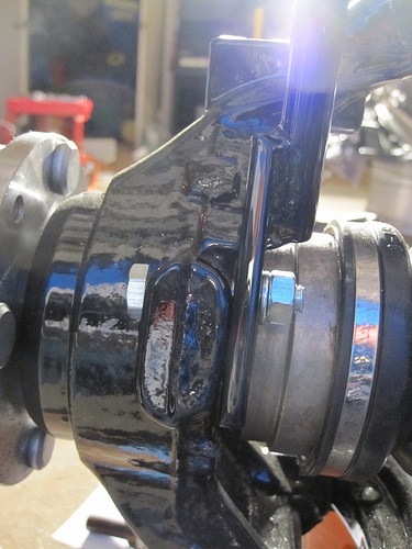
Rear corner, front/rear mount
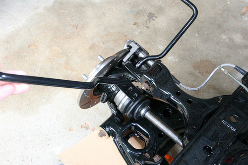
The front mount on the rear corner installs the same way as the one up front – bolts to top caliper bolt)
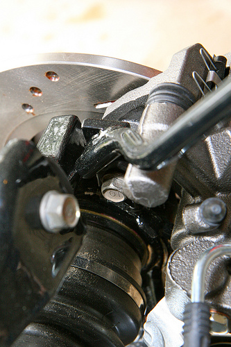
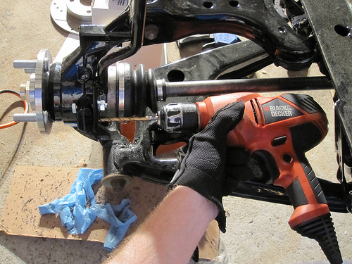
Rear corner, rear mount
Drill two holes and use bolts with locking washers and/or nylock nuts to secure to the nub in the rear hub.
First hole drilled:
Drilling second hole:
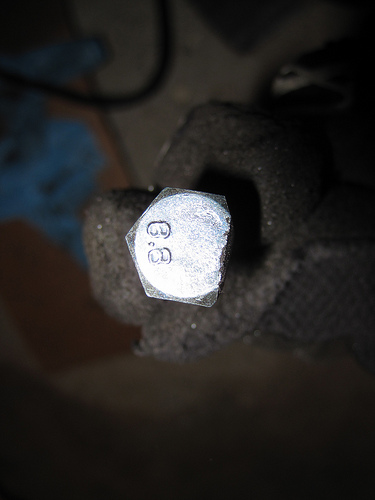
Note 1: You may want to consider grinding or filing the side of the nub flat for a better fit.
Note 2: Be aware of how close you drill the mounting holes to the center of the hub. If you drill the holes too close to the center of the upright you may have to grind down the top of your bolts to make them fit. Example:
In the case that you are using a Miata donor that had ABS, or if you have a Miata that does not have a nub on the rear upright, you may need to fabricate a small steel angle bracket like this: